|
|
|
(Note: Subscribers to the email list receive the update a few days earlier than it is posted on the website. Email address privacy is always respected.) Public Viewing of the Maiden Launch Our current schedule calls for transferring the rocket to the pad in September, performing a short duration vehicle hold down firing and launching as soon thereafter as possible, without compromising safety or reliability. We will not launch until all engineers are two thumbs up, so that date may get pushed back. Since this is a high energy, orbital flight, Air Force range safety has a minimum keep out radius of at least 2 miles. However, Falcon I is seven stories tall with an 85,000 lb vacuum thrust engine and a long, bright LOX/RP flame tail, so the launch will definitely be worth seeing. Launch Manifest
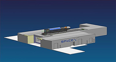
Kistler Sole Source Contract The best destination for those now unallocated tax dollars is open access, performance based contracts (a.k.a. prizes) under the NASA Centennial Prize program. If that is done, it will do wonders to invigorate commercial space development and spur new entrants into the orbital space launch business, just as the X Prize has done for sub-orbital. SpaceX Launch Pad at Vandenberg Air Force Base We do not use a permanent tower on the pad, employing instead our mobile erector/launcher platform. This is stored in a protected environment when not in use, so is not subject to weather damage and corrosion. This makes our maintenance costs very low and minimizes time spent on the launch pad, which in turn reduces our launch operations costs. We can prepare the entire rocket for launch in the controlled environment of our factory, rather than do final assembly at the launch site. Right now, all the electrical and communications wiring is in process of being installed and connected to the base grid. In addition, there is a lot of plumbing work to connect liquid oxygen, RP-1 kerosene, helium and nitrogen. These feed into the quick disconnect umbilicals on the rocket, which detach as the rocket lifts off. The water deluge for heat and noise suppression on launch will just use standard base water pressure, as Falcon I doesn’t need anything more to meet specifications. The CAD solid model below shows what Falcon I will look like on the pad with the mobile launcher, before it is erected for flight:
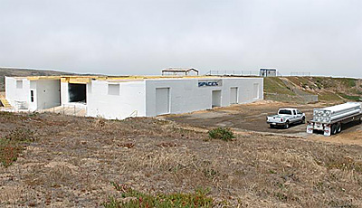
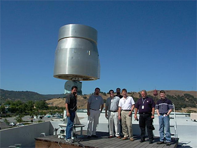
Here you can see an actual picture of Space Launch Complex - Three West (SLC-3W), our home at Vandenberg, under construction. Lockheed, our next door neighbor at SLC-3E, is preparing their Atlas V pad for launch. They have been good, courteous neighbors and hopefully Lockheed sees us the same way.
A tremendous amount of progress was made on the technology development front, as described below. Major milestones include: Merlin fully integrated engine firing with flight tanks, stage separation tested, fairing separation tested and most of the flight avionics & antenna pattern tested. Elon
Propulsion All the unit testing done on the thrust chamber, turbo-pump, as well as cold flows done on the tanks and associated plumbing paid off in a very smooth integration. The start sequence with the turbo-pump is actually more benign for the thrust chamber assembly than the horizontal test stand, where the chamber is pressure fed and receives a slam start. With an improved fuel manifold under construction (the old design cracked during testing), this clears the way to enter the engine qualification program, which is somewhat analogous to the beta test period for software. We know the engine works, we just need to make sure it always works and intend to put in the time to ensure that’s true. Merlin is not just the main engine for Falcon I, but will also serve
as the main engines for Falcon V, so it’s all the more important
and worth the investment to ensure that the engine is rock solid reliable.
However, we are sufficiently confident at this point that we have enough
engines in the manufacturing loop for both Falcon I and the first flight
of Falcon V. First firing of five integrated engines on flight tanks for
Falcon V is scheduled for early 2005.
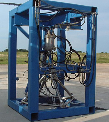
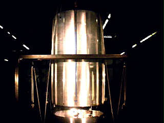
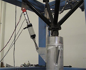
Thrust Frame The corner fittings are precision machined and then welded under argon to the gun drilled tubes. The whole frame only weighs 74.8 lbs and is shown below going through structural qualification. We loaded it to 150,000 lbs (almost twice maximum flight load) in the axial direction and applied max gimbal and TVC loads. Nine limit and ultimate load cycles were applied with no indications of yield (strains all returned to zero).
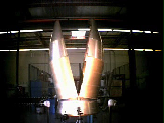
Structures Fairing Separation For a separation system, we use dual-initiated, non-explosive separation
nuts to hold the halves together. When these fire, a pair of pneumatic
pushers rotate each half over a partial hinge, resulting in a very precise
separation arc that ensures neither the payload nor the rocket will be
touched by the departing fairing. Since there are no explosive bolts used
here and the separation itself is gentle, no meaningful shock load is
imparted to the avionics or satellite payload.
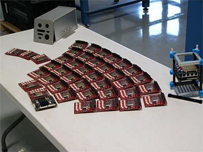
Stage Separation The test proved that the stage separation system functions properly and produces a more than adequate impulse to clear the second stage engine from the first stage during flight. We’ve also tested separation with an offset center of mass and one of the separation bolts firing late and all results are positive. If the second stage engine nozzle does hit the interstage on exit, the worst that will happen is that the niobium nozzle will be dented and immediately undent upon ignition. We chose a refractory metal nozzle over a carbon-carbon nozzle for exactly that reason. The latter will crack like a coffee cup on impact (a la the Shuttle wing leading edge). Avionics, Guidance and Control The red relay boards pictured below are the computer's interface to the rest of the rocket (arranged in theater seating). The computer controlling the rocket is the green board at the lower left. We are not 100% certain, but this is probably the most powerful rocket flight computer in the world, since it is the most recently designed and the only one to use current 21st century technology. It is certainly much more powerful than what’s used on the Space Shuttle. The flight relay boards (FRBs) are the arms, legs, eyes and ears of the flight computer, doing things like issuing the deploy command to the payload, collecting data from the IMU, issuing commands to the pressure controllers, collecting analog sensor data, actuating valves and firing the stage separation bolts. The aluminum enclosure on the upper left houses the boards and the shock mounted cage on the right is what holds them in the deck.
We also completed the antenna pattern test at EDO using a radio true mockup of the avionics bay and surrounding sections. The rocket is truly a flying radio station, with two C-band, four S-band, two UHF and two GPS antennas, as well as a beacon antenna on the first stage for location by the recovery ship.
In the last few months we also completed design, fabrication and testing of our lightweight electro-mechanical thrust vector control system for the upper stage. For our first stage, we use Moog hydraulic cylinders, but could not find a suitable unit at reasonable cost for the upper stage and were forced to build our own. This has worked out well as the whole actuator, including motor, heat sink, gearbox, position sensors and attachments weighs only 5.25 lbs (less than even the most expensive alternative) and is built in-line. It is capable of moving a 7500 lbf rocket engine at 4 inches per second with 800 lbs of force.
|
|